🔥 The PWHT Alternative
Post-weld heat treatment (PWHT) has long been regarded as the most reliable method for reducing residual stresses and tempering brittle microstructures formed during the welding of carbon steels and low-alloy steels. However, full PWHT is often impractical or impossible during repairs of in-service equipment, large pressure vessels, pipelines, or confined components.
📖 What Is Temper Bead Welding?
The core principle of TBW is to use subsequent weld passes to intentionally reheat and temper the hard, untempered microstructures (typically martensite) formed in the heat-affected zone (HAZ) of earlier passes. Instead of applying external heat, the welding arc itself provides controlled thermal cycles that refine grains and reduce hardness.
Why is Temper Bead Welding Needed?
Limitations of PWHT in Field Repairs
API and industry experience acknowledge that PWHT is not always feasible, especially for repairs on pressure equipment in refineries, power plants, and petrochemical facilities due to:
- Equipment size or complex geometry.
- Strict in-service operation constraints.
- Risk of distortion or metallurgical damage to adjacent components.
- Severe safety, cost, and downtime considerations.
Metallurgical Risks Without PWHT
Welding ferritic steels without any form of heat treatment or controlled tempering can lead to catastrophic failures. TBW directly addresses these risks by engineering the thermal history:
- Excessive HAZ Hardness: Prevents brittle fracture points.
- Reduced Fracture Toughness: Restores impact energy absorption.
- Hydrogen-Assisted Cracking (HAC): Reduces the susceptibility to cold cracking.
🔬 How Temper Bead Welding Works
From a metallurgical perspective, when steel adjacent to a weld is heated above the A₁ transformation temperature, austenite forms and transforms upon cooling. Rapid cooling can produce highly brittle, hard martensite in the coarse-grained Heat-Affected Zone (HAZ).
Temper bead welding mitigates this by subjecting these exact regions to subsequent tempering thermal cycles from later weld beads. Peer-reviewed studies confirm that TBW can achieve acceptable hardness and fracture toughness equivalent to—or even better than—PWHT in some steels.
- Significantly reduces martensite hardness.
- Promotes essential carbide precipitation.
- Restores and improves both toughness and ductility.
Thermal Challenges
In wet or underwater welding, the surrounding water acts as a powerful heat sink, making preheat impossible. Rapid heat extraction leads to high cooling rates, promoting hard, brittle microstructures and increasing hydrogen-assisted cracking risks.
Principle of the Sequence
Successive weld beads are deliberately placed in controlled positions relative to preceding beads. The heat from the later bead is used to specifically reheat and temper the HAZ produced by the earlier bead. Overlap positioning is critical for success.
Hardness & Toughness
In documented platform steel trials (0.40 wt% CE), standard welds hit unacceptable HAZ hardness values of >450 HV. When proper TBW was applied, hardness dropped to ~300 HV. Charpy V-notch toughness continuously improves with each controlled pass.
Hydrogen Control Mechanism
An often overlooked benefit: while the temper bead is in a high-temperature austenitic state, it acts as a hydrogen sink. Hydrogen migrates from the crack-susceptible HAZ into the hotter, ductile weld metal, significantly lowering local concentrations.
⚠️ Practical Limitations & Skill Requirements
Despite its immense advantages for avoiding PWHT, the technique is as dependent on operator skill and procedural discipline as it is on the welding parameters themselves. Successful application requires:
- Reasonable visibility, which is a major challenge in underwater environments.
- Strict, unwavering control of bead placement and overlap ratios.
- A well-trained welder (or welder-diver) capable of consistently reproducing the exact required sequence and positioning over long periods.
🛠️ Primary Types of Temper Bead Welding
The core objective of all Temper Bead Welding variations is to carefully deposit each weld layer so that the thermal cycle of the subsequent pass tempers the previous bead and the underlying Heat-Affected Zone (HAZ). This controlled reheating reduces hardness and restores toughness. There are five primary techniques utilized in the industry:
Half Bead Technique
In this method, the first weld layer is deposited and then partially ground or machined away. The second bead is then deposited directly over the remaining half. This mechanical removal and subsequent reheating refine the microstructure and significantly reduce hardness in the root area.
Consistent Layer Technique
Each weld layer is deposited with strictly controlled and uniform bead sizes, consistent spacing, and identical heat input. This precise uniformity ensures that the tempering effect from the next pass penetrates evenly across the entirety of the previous layer.
Alternate Temper Bead Technique
Instead of continuous passes in a single direction, weld beads are deposited in an alternating or staggered sequence. This spatial distribution of heat prevents localized thermal buildup and minimizes the concentration of residual stresses.
Controlled Deposition Technique
Often used synonymously with TBW, this method focuses on the strict, documented control of all welding parameters—including heat input, travel speed, amperage, bead placement, and interpass temperature—to engineer the perfect tempering gradient.
Weld Toe Tempering
Specific, additional tempering beads are strategically placed adjacent to the weld toe area. Because the weld toe is a common stress raiser, these targeted passes soften the localized HAZ and reduce residual stresses where cracking risk is the absolute highest.
Master the Procedures
Looking for a deeper dive into the specific parameters, qualification requirements, and execution of these methods?
Selected References
- ASME Section IX – QW-290 Temper Bead Welding
- API RP 582 – Welding Guidelines for the Chemical, Oil, and Gas Industries
- Sperko, W.J., Exploring Temper Bead Welding, Welding Journal
- Kim & Prince, Temper-Bead Weld HAZ Properties, ASME Journal of Engineering Materials
- Stewart & Alexandrov, HAZ Hardness Response in Temper Bead Welding, Elsevier
Sample Temper Bead Welding Procedure (TBW)
This interactive procedure outlines a sample temper bead welding method suitable for repairs where post-weld heat treatment (PWHT) is not performed. It is intended for training, specification guidance, and engineering reference.
1. Purpose
This procedure defines the requirements for performing temper bead welding as an alternative to PWHT. Controlled bead sequencing, heat input, and interpass temperature are used to temper the heat-affected zone and achieve acceptable hardness and toughness.
2. Applicable Codes & References
- ASME Boiler and Pressure Vessel Code – Section IX
- ASME Section XI (where in-service repairs apply)
- Applicable ASME Code Cases for temper bead welding
- Owner / Client specifications and approved drawings
3. Base Materials & Scope
- P-No. 3 Group 3 ferritic steels
- Dissimilar welds to P-No. 43 materials
- Previously deposited F-No. 43 weld metal
4. Welding Process & Consumables
- Process: GTAW (Machine / Automatic)
- Current Type: DC, pulsed
- Filler Metal: ERNiCrFe-7 (UNS N06052), F-No. 43
- Shielding Gas: Argon (welding grade)
5. Preheat & Interpass Temperature Control
- Minimum base metal temperature: 50°F (10°C)
- Interpass (Layers 1–3): Max 150°F (65°C)
- Interpass (Remaining passes): Max 350°F (175°C)
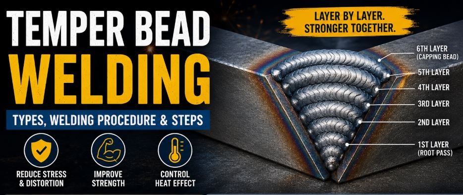
6. Temper Bead Layer Sequence
Layer 1 – Buttering Layer
- Single GTAW layer deposited on ferritic base metal
- Controlled low heat input
Layer 2 – First Tempering Layer
- Fully covers Layer 1
- Outermost bead located 1/8″–1/4″ from Layer 1/base metal interface
Layer 3 – Second Tempering Layer
- Fully covers Layer 2
- No extension beyond outer edge of Layer 2
- Total thickness of Layers 1–3 ≥ 1/8″
7. Heat Input Control
Heat input shall be calculated and controlled using the following formula:
8. Post-Weld Activities
- PWHT shall not be performed
- Post-weld soaking is prohibited
- NDE shall be performed per governing code requirements
9. Limitations & Good Practice
- Temper bead welding is not a universal substitute for PWHT
- Strict control of hydrogen sources is mandatory
- Use only qualified welders and approved procedures
🔥 Supplementary Heating Methods
In some underwater welding applications, chemical heat-generating consumables, such as thermite-based electrodes, have been used as supplementary heat sources. These consumables can provide localized post-pass heating to further temper the HAZ and reduce hydrogen cracking. Trials on steels with carbon equivalents greater than 0.40 wt% have shown that the use of such electrodes after each pass can significantly reduce cracking, particularly when used alongside a strict temper bead welding sequence.
Codes & Standards Governing TBW
📘 ASME Section IX
ASME Boiler and Pressure Vessel Code (QW-290) provides detailed requirements for the qualification of temper bead procedures.
- Introduced formal TBW rules in the 2004 edition.
- Specifies exact bead placement and sequence control.
- Requires overlap of 25–75% and strict hardness testing.
🛢️ API RP 582
API Recommended Practice 582 recognizes TBW as an industry-accepted technique for repairs when PWHT is impractical.
- Widely referenced in oil, gas, and chemical processing.
- Aligns heavily with ASME Section IX for qualifications.
- Standardizes control across field repairs.
🌍 International Practice
Temper bead welding is recognized and adopted across multiple global jurisdictions and specific heavy industries.
- Adopted within ISO-aligned fabrication practices.
- Standardized in nuclear and power industry repairs.
- Included in utility and owner-operator specifications worldwide.
Process Control & Verification
⚙️ Key Welding Variables
Temper bead welding is a highly controlled process. ASME and industry guidance emphasize that bead overlap and pass reheating patterns are critical. Strict management is required for:
- Heat input and travel speed.
- Bead size, shape, and placement.
- Pass sequencing (e.g., half-bead or consistent overlap).
- Interpass temperature control.
🔬 Qualification & Verification
Hardness control is the principal acceptance criterion, supported by rigorous metallurgical examination to verify effective tempering. Procedures are qualified through:
- Procedure Qualification Records (PQRs).
- Macroetch examinations.
- Extensive HAZ hardness testing.
- Detailed metallographic evaluations when code-required.
Applications & Limitations
🏭 Typical Applications
Studies from the nuclear and power generation sectors demonstrate long-term service performance of TBW repairs when properly qualified and executed. It is routinely applied in:
- Pressure vessel and in-service boiler repairs.
- Cr-Mo steel piping systems.
- Nozzle-to-shell weld restorations.
- Nuclear power plant nozzle and penetration repairs.
⚠️ Engineering Limitations
While incredibly powerful, temper bead welding requires engineering judgment. Owner/operator approval and code compliance must always be confirmed before application.
- Does not relieve all residual stresses like full PWHT.
- Is not a universal substitute where PWHT is code-mandatory for specific service conditions (e.g., severe sour service).
- Requires highly experienced welding engineers and specialized, trained welders.
The Future of Controlled Repairs
Temper bead welding is a proven, code-recognized, and metallurgically sound technique that allows engineers to manage HAZ properties when PWHT is impractical. Supported by ASME codes, API recommended practices, and decades of research and field application, TBW has become an essential tool for modern repair welding and asset integrity management.
At Heat Treatment Masters, understanding and applying advanced techniques such as temper bead welding enables safer repairs, reduced downtime, and extended equipment life—without compromising metallurgical integrity.